Thursday, February 18, 2016

[Article Sharing] Fitness-for-service in Pipeline

Fitness-for-service assessment of unpiggable pipelines | Pipelines International


Source: http://pipelinesinternational.com/news/fitness-for-service_assessment_of_unpiggable_pipelines/053611/


Advanced ultrasonic in-line inspection tools provide accurate, repeatable, 100 per cent coverage data that can be used to manage pipeline reliability.
Pipeline operators have long been aware of the need to manage and maintain the integrity of their systems. Recent advances and proven deployment of compact, highly accurate ultrasonic inspection tools for unpiggable and difficult-to-inspect pipelines, in addition to engineering assessment, allow operators to analyse and make decisions that affect continuing reliability.

Quest Integrity Group has developed a number of leading-edge solutions for the inspection and assessment of unpiggable pipelines. InVista is an ultrasonic, fully self-contained, free flowing in-line inspection tool. Unlike other systems, it provides direct measurement of anomaly characteristics for superior pipeline integrity assessment.

The tool detects internal and external corrosion in addition to the dimensional change in difficult configurations, including 1D bends. The tool is easily launched and bi-directional, and is designed to provide high-resolution measurement data of axial position, geometry, and wall thickness.

Fitness-for-service assessment

Fitness-for-service assessment is a multi-disciplinary approach to evaluate structural components to determine if they are fit for continued service. Pipelines may contain flaws or other damage, or may be subject to more severe operating conditions than the original design anticipated. Quest Integrity Group’s LifeQuest pipeline assessment solution uses API 579-1/ASME FFS-1 fitness-for-service methodology to deliver an assessment of the pipeline for continued operation at defined maximum allowable operating pressure. An evaluation of remaining life and/or inspection intervals may also be part of such an assessment.

[Article Sharing] Pipeline Bend or Elbow

Pipes and Bends – An Essential Guide for Second Engineers | Marine Insight


Source: http://www.marineinsight.com/tech/pipeing/pipes-and-bends-an-essential-guide-for-second-engineers-part-2/


Bend or Elbow

Pipe Bend
There is always a doubt about the terms bends and elbows on ships. They are frequently used as synonyms. The difference between them is as follows:
  1. Bend is a generic term for any offset or change of direction in the piping. It is a vague term that also includes elbows.
  2. An elbow is an engineering term and they are classified as 90 deg or 45 deg, short or long radius.
  3. Elbows have industrial standards and have limitations to size, bend radius and angle. The angles are usually 45 deg or 90 degrees. All others offsets are classified as pipe bends.
  4. Bends are generally made or fabricated as per the need of the piping; however elbows are pre fabricated and standard, and are available off the shelf.
  5. Bends are never sharp corners but elbows are. Pipe bending techniques have constraint as to how much material thinning can be allowed to safely contain the pressure of the fluid to be contained. As elbows are pre fabricated, cast or butt welded, they can be sharp like right angles and return elbows which are 180 degrees.
  6. Elbow is a standard fitting but bends are custom fabricated.
  7. In bends as the pipe is bent and there is no welding involved, there is less pipe friction and flow is smoother. In elbows, the welding can create some friction.
  8. All elbows are bends but all bends are not elbows.
  9. Bend has a larger radius then elbows.
  10. Generally the most basic difference is the radius of curvature. Elbows generally have radius of curvature between one to twice the diameter of the pipe. Bends have a radius of curvature more than twice the diameter.

Short Radius and Long Radius

Elbows are again classified as long radius or short radius elbows. The difference between them is the length and curvature. A short radius elbow will be giving the piping a sharper turn than a long radius elbow.
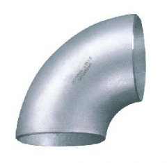
90 degree short radius elbow
  1. In a long radius elbow the radius of curvature is 1.5 times the nominal diameter. In a standard elbow the radius of curvature is 1.0 times the nominal diameter of the pipe.
  2. Long radius elbows give less frictional resistance to the fluid than the short elbows.
  3. Long radius elbows create lesser pressure drop than short radius elbows.
  4. Short radius is less costly than long radius elbows.
  5. The short radius elbows are used where there is scarcity of space.
90 degree stainless long radius elbow
In addition to this classification the elbows are 45 degrees, 90 degrees and 180 degrees also called as a return elbow.
180 degree elbow
The 45 degrees elbow turns the fluid /piping at 45 degrees and so on.
45 degree short radius elbow

Miter bends

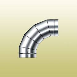
Another type of bend is a Miter bend. A Miter bend is a bend which is made by cutting pipe ends at an angle and joining the pipe ends. A true miter bend is a 90 degree bend made by cutting two pipes at 45 degrees and joining them by welding. Similarly three pipes cut at 22.5 degrees will give a 90 degree miter bend.
Miter Bend

[Article Sharing] Subsea Pipeline Tie-in

Connection Systems & Tie-In | Kongsberg Gruppen


Source: http://www.kongsberg.com/en/kogt/products%20and%20services/subsea%20products%20and%20systems/connection%20systems%20and%20tie-in/


Thor Horizontal Tie-in


The Thor Tie-In System covers a wide range of subsea connections and is applicable for all horizontal tie-in purposes regardless of pipeline size. It can be applied to both rigid and flexible spools as well as to direct pipeline tie-in. The system can be configured for mono-, dual- and multibore lines in addition to pressure caps and pig launchers/receivers.

It is the simple and robust design that makes the Thor Tie-in so attractive. It provides high structural capacity with a unique and patented method of transferring parts of the external moments into the supporting structure to reduce loads on connectors, piping and adjacent valves. Its compact design reduces inventory and is easy to machine, assemble and install.

The system is installed by simple ROV carried tools, these tools are available for rent or purchase, requiring only one supervisor per shift.

The Thor Tie-in is field-proven and in operation. KONGSBERG has delivered twelve tie-in systems for installation of rigid spools on the pipelines between the Edvard Grieg and Ivar Aasen jackets and also to the Hibernia oil field in the North Atlantic.


Vertical Tie-in


A vertical tie-in system has been developed to cater for all vertical tie-in needs.

The system is mechanically simple and all the required utility equipment, such as tools for hub cleaning, seal replacement and a pull down/pull out tool, are included. Suitable for both flexible and rigid spools, the system is landed and initially aligned on guideposts, while water dampers and a fine lowering arrangement ensure a smooth landing on the hub. Our vertical tie-in system is also field proven and in operation. 

Customised Tie-In

KONGSBERG has conducted several customised tie-in projects. These have primarily dealt with modules on subsea structures and very large bore tie-ins. These system solutions are characterised by robust solutions with high moment capacity and minimum operational cost.

[Article Sharing] Pipeline Route Selection

Survey data vital to selecting routes for subsea pipelines | Engineer Live


Source: http://www.engineerlive.com/content/21905#.VMzeBcex4ws.wordpress


Long subsea pipelines need a safe and stable route to shore. Pat Fournier, Senior Geophysicist with Australia's Neptune Marine Services, explains the need for good quality survey data from beneath the seabed.

Australia's North West Shelf (NWS) is an isolated offshore geographic province extending 2400km along the northwest margin of the continent and is Australia's largest oil and gas region. Four major sedimentary basins occur along the shelf, namely the Carnarvon, Canning, Browse and Bonaparte, from south to north respectively. The southern margin of the NWS is approximately 1200km north northwest of Perth, the capital city of Western Australia and the administrative centre for most exploration activity and associated oil field services.

Since the discovery of oil in Australia in 1953 at the Rough Range-1 well, onshore Carnarvon Basin, interest in oil and gas exploration has increased. In 1964 oil was discovered on Barrow Island and the NWS continued to grow and eventually became Australia's premier oil and gas province replacing Victoria's Gippsland Basins.

In the 1960s and 1970s regional offshore geological and geophysical exploration of the NWS led to the discovery of natural gas and condensate deposits in the Carnarvon, Browse and Bonaparte Basins, commencing with the Rankin discovery in the early 1970s. With gas replacing fuel oil in Australian homes and factories, increasing global energy demands, and LNG exports becoming a more viable source of income for the Australia economy, oil and gas companies and their export partners are looking to further exploit the large natural gas reserves in the Australasian region and specifically along the NWS.

Australia currently has two LNG processing plants; the North West Shelf Venture (NWSV) in Karratha and the Darwin LNG Plant, that deliver gas to local and international markets. These two facilities are located approximately 1800km apart along one of the most natural gas rich and remote coastlines in the world. The remoteness of the NWS is becoming less of a deterrent to investors as infrastructure develops in the region (with the aid of increased government support), and the large size of new natural gas discoveries offsets the high financial commitment required by the oil and gas companies to develop their fields.

The new large natural gas discoveries along the NWS have occurred towards and beyond the 200m isobath (shelf break) requiring the design and construction of long subsea pipelines to deliver the gas back to the coast for processing and export. The new subsea pipelines can either tie back to the existing LNG plants, or the oil and gas companies can incorporate the design of new processing facilities as part of their proposals. Because of the large investment commitment these development projects pose for oil and gas companies, the aim is to mitigate the potential of damaging their assets both during installation and once they are installed on the seabed. Part of this involves contracting hydrographic survey companies to map the proposed subsea pipeline routes to avoid potential pipeline instability and damage.

One such company specialising in this work is Neptune Marine Services based in Belmont, Western Australia. Neptune Marine Services is established as one of Australia's leading providers of integrated engineered solutions to the international oil and gas, marine and renewable energy industries. Neptune Geomatics, a subsidiary of Neptune Marine, is a hydrographic survey company specialising in MODU positioning, geophysical site surveys, pipeline route and cable route surveys and offshore construction positioning support services.

In 2008, Neptune Geomatics was awarded a contract to survey a proposed 870km subsea gas pipeline route traversing both the Browse and Bonaparte Basins and terminating in Darwin Harbour. The pipeline is designed to deliver gas to a new processing facility in Darwin. The remoteness and duration of the proposed survey work, coupled with the tight reporting deadlines to tie in with the front-end engineering design (FEED) of the project, required reliable and proven survey equipment to be used during the campaign.

The objectives of the survey were to obtain reliable sub-bottom profiling data to accurately map the shallow geology in the survey area of >5000 line km through which the proposed route would run. The Applied Acoustics' Sub-bottom Profiler, the CSP-D 2400 was the preferred energy source to power the Applied Acoustics' AA301 Boomer for the duration of the survey. The CSP-D 2400 charged at 1000 joules/second for a continuous two month period, with no equipment faults. This proved to be a significant advantage during the survey as it provided the survey crew and pipeline engineers with good quality data to assist pipeline route planning and design.

The efficient and reliable progress achieved during the route survey allowed for further site survey work in the field to investigate the suitability of the shallow geology for the planned seabed infrastructure. The objectives of the field work required the acquisition of sub-bottom profiler data in increased water depth while achieving approximately 150m sub-seabed acoustic penetration. During this phase of the survey, the Applied Acoustics' Squid 2000 was teamed to the CSP-D 2400. The CSP-D 2400 charged at 1500 joules per 1.5 seconds for a continuous three week duration, with no equipment downtime, and assisted in acquiring good quality sparker data to the required depths and the client's objectives.

Due to the success of the survey campaign, Neptune Geomatics will continue to use the proven and reliable sub-bottom profiler equipment provided by Applied Acoustics Engineering to meet its client's objectives. Easily installed and operated, the CSP-D 2400 energy sources generate a safe energy supply. In the two years since purchasing the units, Neptune Geomatics has enjoyed repeatable, reliable energy outputs to towed boomer and sparker sound sources and remains confident moving forward with the technology into the future.

[Article Sharing] Pipeline On-Bottom Stability

Breaking new ground in pipeline on-bottom stability design | The Australian Pipeliner


Source: http://pipeliner.com.au/news/breaking_new_ground_in_pipeline_on-bottom_stability_design/063943/


Test section of the O-Tube facility
The need to better understand pipeline stability in the unique environment of Western Australia’s North West Shelf has lead to the establishment of a research facility in Perth that is attracting worldwide interest.

In February this year, the O-Tube – a closed-loop channel of water that can simulate hydrodynamics near seabed generated by tropical cyclones and their effects on pipeline stability – was used commercially for the first time by researchers and engineers from the University of Western Australia (UWA) and Atteris, on behalf of Woodside Energy.

The team has been running a series of tests over a four- to five-month period to assess pipeline stability on mobile seabeds. The north of Australia is subject to frequent severe tropical cyclones, and the continental shelf comprises unique seabed materials, including carbonate marine sediments. The O-Tube facility provides an opportunity to better understand the physics behind the behaviour of subsea pipelines on these seabed conditions under extreme hydrodynamic loadings.

In 2005, Woodside engaged Atteris to undertake pipeline stability studies. Theoretical assessments comprised studies of pipeline behaviour as well as seabed behaviour under extreme storm events such as tropical cyclones. This approach was unique because conventional pipeline on-bottom stability design methods ignore seabed instability occurring during the build-up, peak and ramp-down of a storm. This work culminated in the concept of building a brand new laboratory testing facility in which the three-way pipeline on-bottom stability processes – fluid-pipe, fluid-soil and pipe-soil – could be physically tested.

UWA designed, supervised the construction of, and commissioned the O-Tube testing facility. UWA has a long track record of delivering specialist numerical and physical model testing services to the offshore hydrocarbon industry, and is regarded worldwide as a state-of-the-art research centre for the subsea pipeline engineering industry.

The O-Tube comprises a closed-loop channel of water driven by an axial flow pump, with a 1 m wide and 1.4 m high test section. This test section allows large diameter pipelines to be modeled at scales of 1:5 to 1:6, with smaller pipelines such as flowlines capable of being modelled at prototype scale. The O-Tube is unique because it can generate a combination of steady and oscillatory flow to produce realistic on-bottom flow conditions.

The pipeline designers have been particularly interested in studying the effects of fluid-soil interaction on pipeline stability. Fluid-soil interaction includes processes such as free field scour, local scour, pore pressure build-up and soil liquefaction. These processes are difficult to predict analytically and can contribute significantly to the overall stability of a pipeline.

The O-Tube is being used to assess the stability of new and existing subsea pipelines and flowlines. These assessments will aim to reduce the level of conservatism associated with current design approaches and minimise costs relating to potentially unnecessary stabilisation measures. The work that has gone into this research program is unique on a worldwide scale, and has attracted the attention of multi-national companies and bodies, including Det Norske Veritas.

The physical model tests performed by a team of engineers and academics from Woodside Energy, UWA and Atteris will pave new ground in the development of a comprehensive subsea pipeline stability assessment method, inclusive of fluid-soil interactions.

The delivery of the O-Tube has been possible thanks to financial contributions from Woodside Energy, Chevron Australia, UWA and the Australian Research Council.

[Article Sharing] Horizontal Directional Drilling

How are pipelines installed across rivers? | Canadian Energy Pipeline Association


Source: http://www.cepa.com/how-are-pipelines-installed-across-rivers#.VM4Jh9w5g0E.wordpress


What is horizontal directional drilling (HDD)?

HDD construction in action (photo courtesy of CCI)
HDD is a trenchless construction method that, in the simplest terms, involves drilling a path underneath a river or other obstacle (like a road) and basically threading the pipeline underneath.

CCI is a Canadian company that specializes in using HDD to construct pipelines that cross bodies of water. Dave Dupuis, the company’s chief operating officer, explained that HDD eliminates the need for equipment to enter the water, like in the open-cut method of installation.

“There is absolutely zero impact in regards to the environment because we are going underneath (the water), so there is no surface disturbance whatsoever for the construction and installation,” said Dupuis, who added that disturbances only occur where the machinery is located and at the exit point where the pipe is joined.

If you want more info on how HDD works, CCI was featured on the TV series “Frontiers of Construction,” and you can download the video on CCI’s site (just scroll to the bottom of the page for the link).

How does HDD protect the environment?

“It’s really the most environmentally friendly method of installation across a water body,” Dupuis explained.

He pointed out that because there is no physical activity inside the water, “fish habitats are not disturbed.”

Riverbank stability is another benefit associated with the HDD construction method.

“There is no disturbance, so there’s no possibility of (the bank) sloping in or eroding into the water body,” Dupuis pointed out.

Wednesday, February 17, 2016

[Article Sharing] Linepipe Manufacture

How Steel Pipes are Made? | Madehow


Source: http://www.madehow.com/Volume-5/Steel-Pipe.html


Design

There are two types of steel pipe, one is seamless and another has a single welded seam along its length. Both have different uses. Seamless tubes are typically more light weight, and have thinner walls. They are used for bicycles and transporting liquids. Seamed tubes are heavier and more rigid. The have a better consistency and are typically straighter. They are used for things such as gas transportation, electrical conduit and plumbing. Typically, they are used in instances when the pipe is not put under a high degree of stress.

Certain pipe characteristics can be controlled during production. For example, the diameter of the pipe is often modified depending how it will be used. The diameter can range from tiny pipes used to make hypodermic needles, to large pipes used to transport gas throughout a city. The wall thickness of the pipe can also be controlled. Often the type of steel will also have an impact on pipe's the strength and flexibility. Other controllable characteristics include length, coating material, and end finish.

Raw Materials

The primary raw material in pipe production is steel. Steel is made up of primarily iron. Other metals that may be present in the alloy include aluminum, manganese, titanium, tungsten, vanadium, and zirconium. Some finishing materials are sometimes used during production. For example, paint may be used if the pipe is coated. Typically, a light amount of oil is applied to steel pipes at the end of the production line. This helps protect the pipe. While it is not actually a part of the finished product, sulfuric acid is used in one manufacturing step to clean the pipe.

The Manufacturing Process

Steel pipes are made by two different processes. The overall production method for both processes involves three steps. First, raw steel is converted into a more workable form. Next, the pipe is formed on a continuous or semicontinuous production line. Finally, the pipe is cut and modified to meet the customer's needs.

Ingot production 

1) Molten steel is made by melting iron ore and coke (a carbon-rich substance that results when coal is heated in the absence of air) in a furnace, then removing most of the carbon by blasting oxygen into the liquid. The molten steel is then poured into large, thick-walled iron molds, where it cools into ingots.
2) In order to form flat products such as plates and sheets, or long products such as bars and rods, ingots are shaped between large rollers under enormous pressure. 

Producing blooms and slabs

3) To produce a bloom, the ingot is passed through a pair of grooved steel rollers that are stacked. These types of rollers are called "two-high mills." In some cases, three rollers are used. The rollers are mounted so that their grooves coincide, and they move in opposite directions. This action causes the steel to be squeezed and stretched into thinner, longer pieces. When the rollers are reversed by the human operator, the steel is pulled back through making it thinner and longer. This process is repeated until the steel achieves the desired shape. During this process, machines called manipulators flip the steel so that each side is processed evenly.
4) Ingots may also be rolled into slabs in a process that is similar to the bloom making process. The steel is passed through a pair of stacked rollers which stretch it. However, there are also rollers mounted on the side to control the width of the slabs. When the steel acquires the desired shape, the uneven ends are cut off and the slabs or blooms are cut into shorter pieces. 

Further processing

5) Blooms are typically processed further before they are made into pipes. Blooms are converted into billets by putting them through more rolling devices which make them longer and more narrow. The billets are cut by devices known as flying shears. These are a pair of synchronized shears that race along with the moving billet and cut it. This allows efficient cuts without stopping the manufacturing process. These billets are stacked and will eventually become seamless pipe.
6) Slabs are also reworked. To make them malleable, they are first heated to 2,200° F (1,204° C). This causes an oxide coating to form on the surface of the slab. This coating is broken off with a scale breaker and high pressure water spray. The slabs are then sent through a series of rollers on a hot mill and made into thin narrow strips of steel called skelp. This mill can be as long as a half mile. As the slabs pass through the rollers, they become thinner and longer. In the course of about three minutes a single slab can be converted from a 6 in (15.2 cm) thick piece of steel to a thin steel ribbon that can be a quarter mile long.
7) After stretching, the steel is pickled. This process involves running it through a series of tanks that contain sulfuric acid to clean the metal. To finish, it is rinsed with cold and hot water, dried and then rolled up on large spools and packaged for transport to a pipe making facility. 

Pipe making

8) Both skelp and billets are used to make pipes. Skelp is made into welded pipe. It is first placed on an unwinding machine. As the spool of steel is unwound, it is heated. The steel is then passed through a series of grooved rollers. As it passes by, the rollers cause the edges of the skelp to curl together. This forms an unwelded pipe.
9) The steel next passes by welding electrodes. These devices seal the two ends of the pipe together. The welded seam is then passed through a high pressure roller which helps create a tight weld. The pipe is then cut to a desired length and stacked for further processing. Welded steel pipe is a continuous process and depending on the size of the pipe, it can be made as fast as 1,100 ft (335.3 m) per minute.
10) When seamless pipe is needed, square billets are used for production. They are heated and molded to form a cylinder shape, also called a round. The round is then put in a furnace where it is heated white-hot. The heated round is then rolled with great pressure. This high pressure rolling causes the billet to stretch out and a hole to form in the center. Since this hole is irregularly shaped, a bullet shaped piercer point is pushed through the middle of the billet as it is being rolled. After the piercing stage, the pipe may still be of irregular thickness and shape. To correct this it is passed through another series of rolling mills.
Seamless pipe is manufactured using a process that heats and molds a solid billet into a cylindrical shape and then rolls it until it it stretched and hollowed. Since the hollowed center is irregularly shaped, a bullet-shaped piercer point is pushed through the middle of the billet as it is being rolled.

Final processing

11) After either type of pipe is made, they may be put through a straightening machine. They may also be fitted with joints so two or more pieces of pipe can be connected. The most common type of joint for pipes with smaller diameters is threading—tight grooves that are cut into the end of the pipe. The pipes are also sent through a measuring machine. This information along with other quality control data is automatically stenciled on the pipe. The pipe is then sprayed with a light coating of protective oil. Most pipe is typically treated to prevent it from rusting. This is done by galvanizing it or giving it a coating of zinc. Depending on the use of the pipe, other paints or coatings may be used.


Quality Control

A variety of measures are taken to ensure that the finished steel pipe meets specifications. For example, x-ray gauges are used to regulate the thickness of the steel. The gauges work by utilizing two x rays. One ray is directed at a steel of known thickness. The other is directed at the passing steel on the production line. If there is any variance between the two rays, the gauge will automatically trigger a resizing of the rollers to compensate.

Pipes are also inspected for defects at the end of the process. One method of testing a pipe is by using a special machine. This machine fills the pipe with water and then increases the pressure to see if it holds. Defective pipes are returned for scrap.